Introduction to: Patterns of Design (III)

If you search this words on google, factory vs builder pattern, you will find thousands of web pages which try to explain the difference between this two patterns.

We could say that the main difference between them, is the type of complexity in creating the product. So, when the product must be created step-by-step, you’d rather use the Builder Pattern. Otherwise, when the product is created in a single action, the Factory Method must be chosen. In this post, we will focus on this last pattern.

Class Diagram for the Factory Method Pattern

The purpose of Factory Method Pattern is to decouple the concrete products from the client, which will be only coupled with an interface of Product. As it can be seen, this pattern is useful when there is a hierarchy of Product.

Actually, a client must only know about the Product interface and the Creator abstract class. He is isolated from the concrete implementations of both Creator and Product.

Now we will see a situation where this pattern could be applied. We need to model a Soda Factory. This factory (Creator abstract class) produces different kinds of soda (soda is the interface, and each kind of it is a concrete class). The Creator is not supposed to know about any kind of soda. Each concrete class, extending Creator, will override the FactoryMethod and will produce an implementation of Product interface. The clients of this model, will know that there is a Creator and a Product interface, but they don’t care about the concrete classes. When using Factory Method pattern, from the client’s point of view, the Product is created as a result of invoking only one method. On the other hand, when the Builder Pattern is used, the creation is made step-by-step.

This table summary may help.

Builder Pattern Factory Method Pattern
There is no hierarchy of Products (or it’s very simple) There is a hierarchy of Products
Products are created step-by-step Products are created only in one step
Subclasses of Builder know about steps of creation Subclasses of Creator will create a concrete type of Product
The creation steps are very clear The creation algorithm may differ from one type of Product to another

Introduction to: Patterns of Design (II)

In this next chapter another type of pattern of design will be introduced, the creational one. There are some differences between this kind of patterns and the behavioral types (a type of last one was described in part one), the most important thing is, while behavioral centers itself on the algorithms and how the object works, the creational pays attention in how the object is created.

We will decide to apply this kind of patterns when we need to focus in the creation of the object, and this creation is a highly complicated process. The concrete pattern shown in this introduction is the Builder Pattern.

The Builder Pattern is recommended when the algorithm for the creation of the object it’s very clear and it composed by very well-defined steps. The complexity of the creation lies on the different algorithms that might be used in the steps. Maybe a little class diagram should help:

Builder Pattern Class DiagramAs we can see in the class diagram, the Director is the only class that knows about the whole creation process. The Director it’s only coupled with the abstract Builder, so it has no dependency on the concrete classes. A concrete Builder class instance must be passed to the Director.

The Director knows which methods of the Builder class must be called, and in which order, what doesn’t know it’s what each method does, of course. Each concrete Builder class model a specific algorithm for the Product creation. In order to ensure that, the concrete classes must override the methods defined in the abstract class, except those ones that are generic enough.

Let’s apply this pattern in a real example, well maybe it isn’t very real, but it will be useful. Imagine that we need to model the Automated Letter Maker. Given a set of concepts (sender, subject, name…) the application must create different kinds of letters (friendly, formal, business letter…). All the letters has the same parts: header, greeting, body, complimentary clause, signature and postscript. Lets put it all together in another class diagram.

Class Diagram for Automatized Letter MakerThe Writer class knows the algorithm for writing a letter, first is the header, then de greeting… and ends with a possible postscript. But this class doesn’t know how to write it in the proper style (formal, business…). Each concrete builder knows how to write each part in the appropriate type. Finally the Letter is the output of any kind of builder.

Why this pattern is suitable for this example?

  • The output it’s always the same: a Letter.
  • The steps of the creation of a Letter are very clear.
  • There are different ways to implement each step.
  • The addition of new types of builders has the less possible impact in the model.

*All diagrams are made with StarUML.

Introduction to: Patterns of Design (I)

The purpose of this post is to try to introduce the Patterns of Design. In this first chapter the Chain of Responsibility will be introduced.

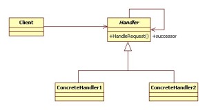
First of all, let’s see the UML class diagram for this pattern:

UML class diagram for the Chain of Responsability Pattern

The purpose of this pattern is giving more than one object the opportunity to handle an event or request. The pattern consists of one abstract class named Handler. This class has a method named HandleRequest, and has an self-relationship called successor. Its goal is to create a chain, so each link has the possibility to handle the request. As you can see in the diagram, the client only “has to know” about the Handler. The only but, it’s that someone has to create the Chain with all its links (each ConcreteHandler). A XML file can be used for this purpose, another possibility is to hard-code the creation of the entire chain.

When a Client calls the HandleRequest on Handler, it’s processed by one ConcreteHandler, which has to decide if the request has to be processed or not. Once processed, it has to decide if the request has to be processed by the next link or otherwise finish the processing.

Filters in Web Applications (which will be introduced in a future post) are an actual example of this pattern. The web.xml is the file that models the chain, in this file it’s stated which classes will set up each link of the chain. In web filters, each HttpRequest it’s processed by the first link (filter), and it has to decide if the request will be processed by the next filter. The order of processing and calling the next link can be reversed, so first of all the link calls the next link in chain and then it will process the request after the callback.

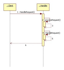
Another real example where I used this pattern: we had to process a document and decide where to deliver it. We knew that more destinations would be added in a future, but we didn’t know the algorithm for the unknown destinations. So we decided to implement a link for each already known destination. Each destination knew how to decide if the document was suitable for it, but had no possibility of not sending the document to the next link. The behaviour of chain was implemented in the HandleRequest in the abstract class, here there is the sequence diagram.

How the chain works

As it’s shown, the abstract class calls an abstract method called processRequest, which does the actual processing of the request, implemented in the concrete classes. After calling this method the next link in chain is called. This order can be reversed, so first call the next chain, and then process the request.  In our case, each link had no possibility of not calling the next link, if this possibility is needed, the processRequest method can return a boolean value to determine if request has to be processed by the next link or not.

*All diagrams are made with StarUML.